FX-SPIDER-40/10 (C-Series)#
Purpose
In this lesson we are learning the main features of the FX-SPIDER-40/10.
FX-SPIDER-40/10 Freely programmable BMS controller (PLC) with 40 I/O-points.#
Technical features#
I/O-Points:
40 integrated I/O-points through Modbus RTU RS-485
- Relay outputs:8 relay outputs on connectors A1..B8. The relays are of the Normal Open type. The maximum load per relay is 6A at 230 VAC or 5A at 30 VDC.
- Universal Inputs:16 universal inputs on connectors C1..D8. can be programmed as voltage signal measurements (0..10V), resistive measurements, indications or alarms.
- Safety loop inputs:8 safety loop inputs on terminals E1..E8.
- Analogue Outputs:Analogue Outputs F1..F8 send out 0-10V signals with an impedance of 1kΩ, at a maximum load of 10 mA.
- Ground & power supply:Ground: I1..J8 connectors are for groung levels.24 VDC out: 13 connectors (G1..G7 and H3..H8) at which it offers 24 VDC out to power field equipment. The maximum total load 36 Watt or 1.50 A.24 VAC out: Optional 24 VAC transformer with maximum load 20VA or 1.0A continuous.
Screen and user interface
10.1” touch screen Integrated web server, history logging, user management…
Communiation
BACnet, Modbus and M-bus communication
Power supply:
Controller comes with a standard European CEE 7/7 plug and is thus powered with 230 VAC. There is an adapter inside the encasing that powers all internal equipment, and also offers 24 VDC through connectors G1..G7 and H3..H8.
USB:
The FX-SPIDER-40/10 has 2 USB ports. With the Update Tool software, the USB1 port can be used to update, consult or reset certain settings that require local intervention. The USB2 port is allocated to the internal router
Serial communication:
The internal I/O’s on the FX-SPIDER-40/10 are connected internally to serial port COM3 on a Modbus RTU loop over RS485. The I/O’s occupy fixed addresses 1..6, but the loop can continue from connectors H1/H2.
More
More technical details can be found on datasheet: Datasheet
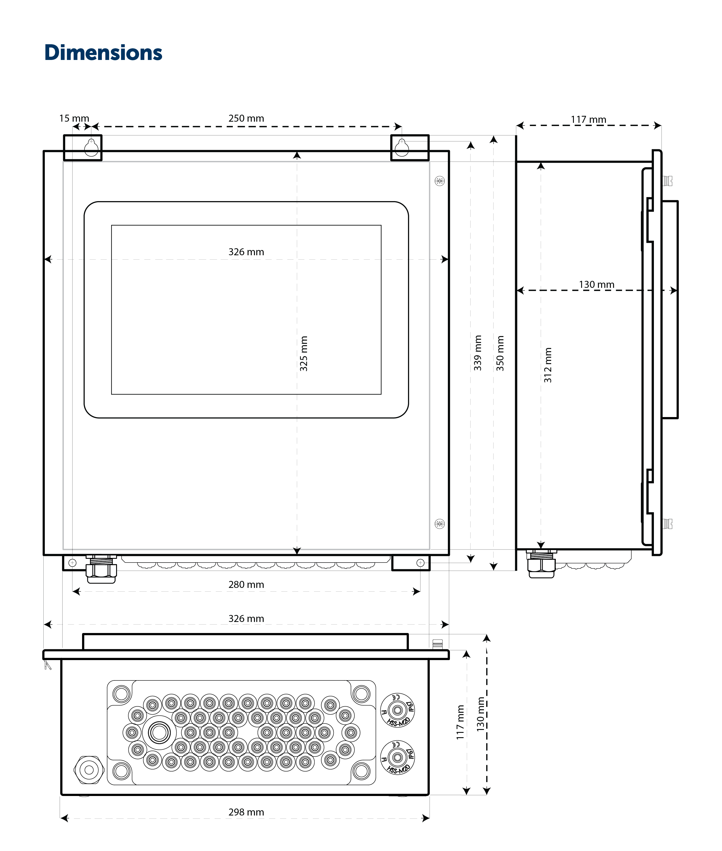
Controller’s physical components#
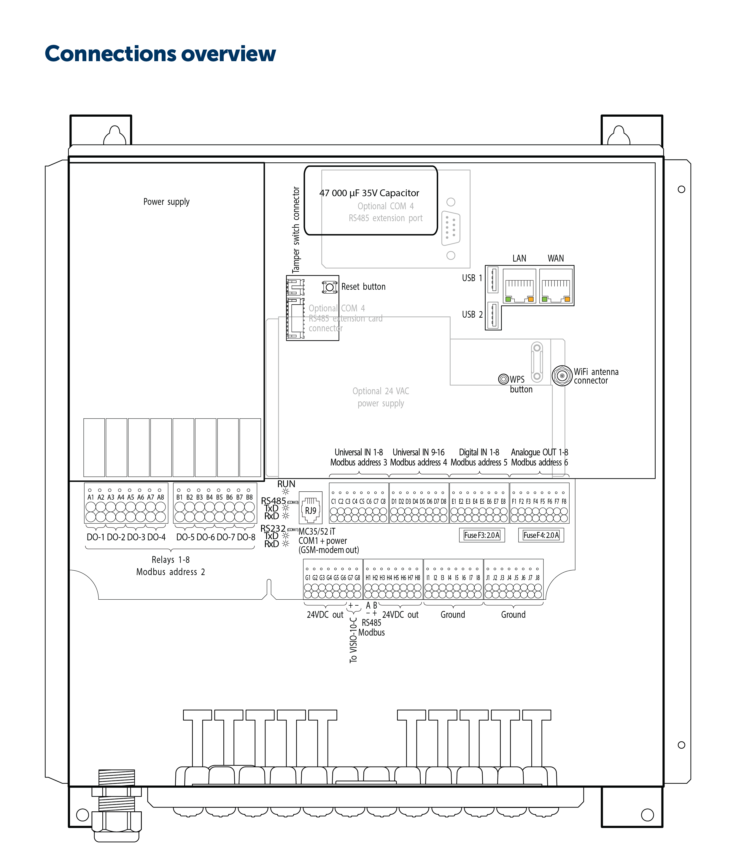
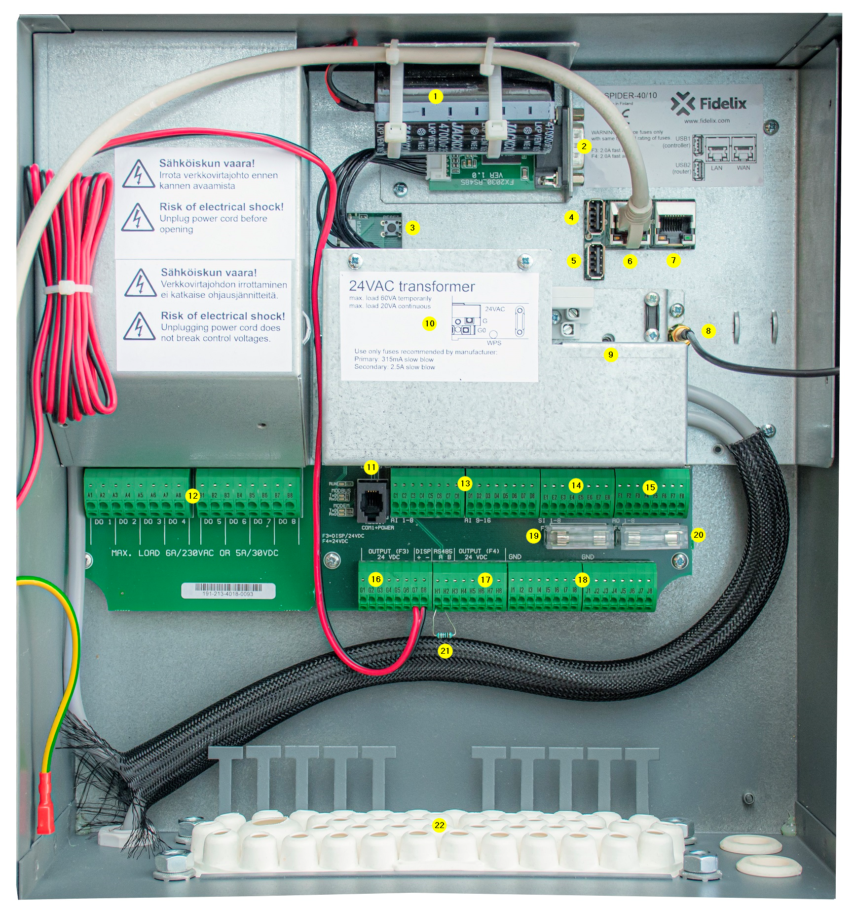
Capacitor to enable “soft shutdown” of the FX-controller upon power interruptions.
COM4 RS485 connector (optional). Use a D-SUB9 cable to connect the 2 wires for Modbus A/B -/+ communication.
Reset button
USB 1 port. Connected to the FX-CPU. Can be used for instance to reset or backup the controller using the Fidelix Update-Tool.
USB 2 port. Connected to the Router module. Here, we can connect a USB-modem with SIM card.
LAN port. RJ45 for network connection to a Local Area Network.
WAN port. RJ45 for network connection to a Wide Area Network (the Internet usually)
WiFi antenna connector.
WPS button for WiFi.
24 VAC - 60 VA secondary power supply for field devices (optional).
GSM-modem output.
8 relays or DO-outputs, connectors A1-B8. Connect up to 6A @ 230V.
16 analogue/universal inputs. Connectors C1-D8, references I1-J8.
8 digital inputs. Connectors E1-E8, references I1-J8.
8 analogie outputs (0..10V control signal). Connectors F1-F8, references I1-J8.
24 VDC outputs. Connectors G1-G6.
24 VDC outputs. Connectors H3-H8.
Common reference/GND connectors I1-J8.
F3 glass tube fuse. 2.0 Ampere fast. Protects the 24 VDC outputs G1-G7.
F4 glass tube fuse. 2.0 Ampere fast. Protects the 24 VDC outputs H3-H8.
120 Ω end resistor for Modbus RTU COM-port 3.
Plastic gland plate with membranes.
Verify your skills:#
Recap:#
Check the datasheet to recap the major features: Datasheet
To train more, you can dig in to manual: Programming manual